How An Atmospheric Dispersion Corrector Works
Over the past few years, there has been a revolution in planetary imaging among amateur astronomers. CCD sensors with high sensitivity have made it possible to rapidly obtain large numbers of short-exposure images of the planets. This coupled with powerful computers has allowed amateur astronomers to image the planets with higher resolution than previously possible.
The main limitation to high-resolution planetary imaging has been atmospheric turbulence. The best views of the moon and planets are generally obtained when they are observed at high elevation angles. When a planet is 30 degrees above the horizon, there is twice the amount of atmosphere to look through as compared with observing the planet at zenith.
Therefore, collecting imagery when the planets are high in the sky is a good strategy. However, unless one lives near the equator, the planets may often be found at lower elevations. For example, Saturn is currently moving into a part of its orbit that will result in low elevation angles for Northern Hemisphere observers during the next 10 years. Also, Mars was seen at low elevations from the United States during its close opposition in 2003.
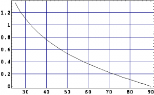
In addition to turbulence, the atmosphere creates another imaging problem referred to as differential atmospheric refraction. In effect, the atmosphere acts as a giant, but very-weak prism. Blue light is bent downward more strongly than red light. This results in a smearing of planetary imagery into a vertical spectrum. The amount of this smearing depends on the planet’s elevation angle. Figure 1 shows a plot of the difference between the red and blue images (dispersion) as a function of the elevation angle.
Table 1 gives a list of dispersion values between the blue wavelength of 486 nm and red wavelength of 656 nm for a ground level temperature of 0°C and 1.0 atmosphere of pressure. Higher pressures and lower temperatures will raise the amount of dispersion, but variations should only be a few percent. Above an elevation of 60 degrees, atmospheric dispersion is not a big problem.
| Elevation
degrees |
Dispersion
arcseconds |
| 30 | 1.10 |
| 35 | 0.91 |
| 40 | 0.76 |
| 45 | 0.64 |
| 50 | 0.53 |
| 55 | 0.45 |
| 60 | 0.37 |
Planetary imagers that obtain red, green and blue imagery using monochrome cameras and spectral filters can align the images to each other and to a large degree eliminate this problem. However, for elevations angles below 45 degrees, the smearing that occurs within each color band starts to become a problem. Also, if one wants to use a wide-band luminance image for high-resolution planetary detail, the smearing over the wide-band becomes a problem at even higher elevation angles.
Unlike atmospheric turbulence, the smearing effect of atmospheric dispersion can be eliminated from captured imagery. Professional astronomers use a device called an atmospheric dispersion corrector (ADC) in the optical path of their telescopes to cancel the spectral image spread. An ADC generally consists of a pair of prisms that introduces a spectral image smear that is equal in magnitude, but opposite in direction to that produced by the atmosphere.
The best place for an Atmospheric Dispersion Corrector is between a Barlow lens and the camera or eyepiece. In this space very little extra image aberrations will be introduced to the optical system. In order to avoid optical aberrations produced by the ADC, the optical system should be slower than f/15. This can be easily accomplished with a Barlow lens.
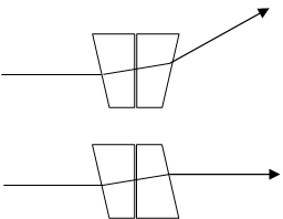
Using many typical video cameras available for planetary imaging, focal ratios between f/20 and f/40 will give the best results. An atmospheric dispersion corrector can be implemented using two wedge prisms. The most common configuration consists of two wedge prisms that are rotated in opposite directions as shown in Figure 2.
In this configuration, rotation of one of the prisms changes the ray angles. In the lower diagram of Figure 2, there is no angular deviation of the ray, but there is a small vertical offset. The upper diagram shows the prism orientation for maximum ray angle deviation. In order to keep the angular displacements in the vertical plane, both prisms must rotate in opposite directions.
In this ADC configuration, the rays of all colors will be deviated in addition to the red-blue differential deviation. This is undesirable, because it creates a change in the telescope pointing direction when the prisms are rotated. Such an ADC was reviewed by Thomas A. Dobbins in the June 2005 edition of Sky & Telescope. The “Planetary Atmospheric Dispersion Corrector” (PADC) was sold by Adirondack Video Astronomy and is no longer available. The conclusion was that the ADC optics worked well, but the “Variable-prism setup requires tedious iterative adjustment.”
The narrow field of view provided with typical webcams and the ADC’s line-of-sight image shifts could easily cause the planets to move outside the field of view. Thus visual evaluation of dispersion, coupled with loss of the planet from the field of view when a prism adjustment was made was a rather frustrating experience. An ADC of similar design is, however, available from Astro Systems Holland.
Another Approach
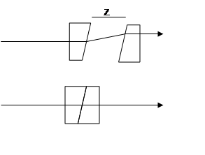
Since that time, another Atmospheric Dispersion Corrector configuration has been developed, the longitudinal configuration as shown in Figure 3.
An ADC using this longitudinal atmospheric dispersion corrector (LADC) configuration is currently in use at the Keck observatory. The advantages of this configuration for amateur astronomers are two-fold: (1) Only one prism needs to move, and (2) the LADC can be calibrated so that iterative adjustment is not required. One simply sets the rear prism position based on the knowledge planet’s elevation angle. The elevation of a planet can be determined using a Planetarium program.
Using this approach, it is not necessary to use visual feedback to adjust the ADC. With this LADC configuration, the longitudinal separation of the rear prism results in vertical displacement of the rays. The amount of displacement is wavelength dependent. The difference in ray height ∆yblue_red between blue and red wavelengths is given by:
![]()
where nblue is the index of refraction of the prisms at a blue wavelength and nred is the index of refraction of the prisms at a red wavelength, α is the angle (in radians) that the back prism surface is inclined and z is the prism separation distance.
For BK7 glass, the difference between the index of refraction between the blue and red wavelengths is equal to 0.00806. A 4-degree angle deviation BK7 wedge prism has a wedge angle α = 7.68 degrees, the above equation becomes:
![]()
In order to determine the prism separation for a given elevation angle, one first reads off the angular separation given in Table 1. Then knowing the telescopes effective focal length, the image shift is determined using the following equation:
![]()
Finally, the prism separation z is determined using the first equation. For example, a planet at an elevation angle of 35 degrees requires and angular shift image of 0.91 arcseconds. Suppose we are using a 200-mm diameter telescope with a Barlow lens with an overall focal ratio of 25. The effective focal length is 5000 mm. The blue-red image shift required is 0.022 mm, and this can be accomplished with a prism separation of 20.4 mm.
Performing these calculations while observing is not required, if an elevation angle scale is included on the device. Starting with the telescope pointing roughly at the target, the observer rotates the LADC so that the prisms will lie in a “vertical” plane. This is straight forward with an “in-line” telescopes, like a refractor, Schmidt-Cassegrain or Dall-Kirkham.
For a Newtonian, the observer would need to move the scope in elevation to determine the ADC rotation that corresponds to the correct “up” orientation. For a Dobsonian, this need only be set once. In the case of the Newtonian, the ADC orientation should be adjusted once every ~ half hour. Then one sets the rear prism position directly using knowledge of the planet’s elevation angle. After that, the observer points the telescope and adjusts focus without any more ADC adjustments. The use of the elevation angle scale therefore eliminates the “tedious iterative adjustment.”
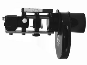
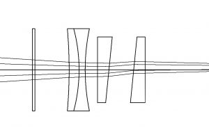
Figure 4 shows a possible layout drawing of an LADC showing a spectral filter and Barlow lens on the left and the focal plane on the right (not shown). Shifting the rear prism to the right results in displacement of the rays upward as can be seen in the diagram. This means that the position of the planet will be shifted in the field of view. However, this shift will typically be less than 0.02 degrees so that the impact on CCD imaging is not a big problem.
Since this type of Atmospheric Dispersion Corrector is not commercially available, the author has assembled one using mostly from off-the-shelf components from Edmund Optics. Figure 5 shows a picture of the finished device. The optical components are the two 25-mm diameter wedge prisms. A mechanical scheme is needed to allow the rear prism to move along the optical axis without rotation or change in camera or eyepiece position. The Edmund Optics cage component system is one way to do this. A number of rings can slide on precision steel rods. Another approach might involve the use of a rack-and-pinion, like an eyepiece focuser. A list of the major components used are shown here.
Part – Quantity – Edmund Part Number
Wedge Prism 4.0 deg vis 0 AR coatings – 2 – #49441
30 mm Cage Mounting Plates- 3 – #85631
25 mm Lens Mount M27.5 15 mm long – 2 – #85588
6X75 mm steel rods – 2 – #85487
C-mount Extension Tube 10 mm – 1 – #54629
Compact C-T Thread Adapter – 1 – #53483
The camera is attached using the C-mount extension tube. Figure 5 shows a Point Grey Research Flea 3 camera attached. The ADC attaches to the telescope using the T-thread adapter. This can be attached to a 2-inch flange or filter wheel.
Since I am currently using a 10-inch f/22 Dall-Kirkham, a Barlow lens is not required. This gives me sufficient space to insert the LADC into the optical path. Amateur astronomers using Schmidt-Cassegrain telescopes would need to insert a Barlow at this point. Different telescopes would require different approaches to integrating the required components. Some telescopes may have insufficient back focus space to make this work. In particular, many Newtonians may not have enough space.
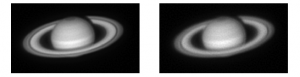
An example of the use of this LADC is shown in Figure 6a and 6b. Here, Saturn is imaged with a 10-inch Dall-Kirkham, using a wide spectral band filter that transmits from 500 nm to 1000 nm. The idea here is to obtain a high signal-to-noise ratio luminance image component to be used with RGB filtered imagery to create a color picture. The wide-band allows higher frame rates, which help to freeze the turbulence. In this case the frame rate was 30 frames per second.
Figure 6a shows the image with LADC and Figure 6b shows an image with no LADC when imaging Saturn with a wide band filter, where Saturn’s elevation was 38 degrees.
This is an extreme case for atmospheric dispersion, due to the wide spectral band. Saturn was imaged at an elevation of 38 degrees. Imagery was collected with two ADC different prism separations. One prism separation corresponds to 38 degrees elevation and the other one for 90 degrees (no ADC).
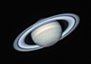
The image processing for both data sets was identical. It can be seen that the Cassini division in Saturn’s rings is more clearly defined for the case where the ADC was set for a prism separation that corresponds to the actual elevation of Saturn. Figure 7 shows a color LRGB picture of Saturn obtained using the LADC described in this article.The elevation of Saturn was 35 degrees and the luminance spectral filter 400 – 1000 nm.
Since many planetary imagers live in places where planetary elevations are typically not high, the need for atmospheric dispersion correction is clear. Imagers who capture RGB images with monochrome cameras and process the video imagery with programs like RegiStax can compensate for the dispersion by allowing the software to align the red and blue images to the green image. This works well for elevation angles above ~ 45 degrees. Here the dispersion within each color band is not too bad.
However, for elevations below 45 degrees and wide-band imaging as shown in Figure 6, the need for optical compensation of dispersion is apparent. In this case, the LADC design can significantly sharpen planetary imagery. Since this type of Atmospheric Dispersion Corrector can easily be calibrated, it is easy to use.
I hope you find this information helpful.
 By Robert E. Majewski:
Dr. Robert Majewski is a retired engineer living in Las Vegas. He has an M.S. and Ph.D. degrees in Physics from the University of Illinois. His career involved testing and calibrating a number of imaging electro-optical systems at the Hughes Aircraft Company and Raytheon Missile Systems. His hobbies include high-resolution planetary imaging and exoplanet transits.
###
 To make it easier for you to get the most extensive telescope and amateur astronomy related news, articles and reviews that are only available in the magazine pages of Astronomy Technology Today, we are offering a 1 year subscription for only $6! Or, for an even better deal, we are offering 2 years for only $9. Click here to get these deals which only will be available for a very limited time. You can also check out a free sample issue here.